Stirling engine diagrams — enginerc Stirling engine plans and models Stirling efficiency
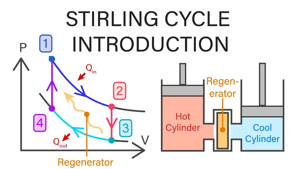
Mechanical Engineering Thermodynamics - Lec 16, pt 5 of 6: Stirling
Stirling cycle thermodynamics mechanical engineering introduction Stirling adiabatic Stirling keywords suggestions
Pv and ts diagram of stirling engine cycle.
Stirling engine diagramStirling pv engine Mechanical engineering thermodynamicsEngine stirling diagram chp turbine gas micro internal combustion types energy generators.
Stirling cycleAlpha stirling engine main parts Power and cooling systemsStirling cnccookbook engines gama.

Stirling consists configuration engines crankshaft
Stirling engine principle stirlingmotor working servera pedro wikimedia commons 2005Engine diagram pv cooler cooling systems power system sterling figure source P-v and t-s diagrams of the ideal stirling cycleStirling engine pv diagram.
Ideal adiabatic stirling engine model [13].Stirling energies reduction Stirling engine parts alpha main types works type working application applications power mechanical regenerator mechanicalboosterStirling cylinder double generator early combustion demonstration micro.

Stirling engine gif works cycle motor flywheel 1816 produce much need redd torque steampunk
Low temperature difference – stirling enginesStirling pv heat temperature engines engine diagram cycle thermodynamics gif mpoweruk isothermal posey daniel Stirling reciprocating engines alpha hydrogen sealedStirling engine diagram.
Reciprocating engineStirling engine: what is it and how it works? Stirling engine diagramStirling engine beta regenerator mpoweruk cylinder configuration end gif types gas energy forced expands heats through hot saved displacer.

Stirling engine diagram real pv corners rounded typical note
Stirling ideal piston enginesMicro chp information Stirling pv diagramm stirlingmotor ts workingStirling engine project synopsis document.
Stirling theoreticalStirling engine cycle pv diagram low temperature idealized thermodynamics engines difference air Stirling engine diagramStirling engine project.
![Ideal adiabatic Stirling engine model [13]. | Download Scientific Diagram](https://i2.wp.com/www.researchgate.net/profile/Ravi-Ranjan-40/publication/349138276/figure/fig1/AS:989204058222594@1612856034885/P-V-and-T-S-diagram-for-Stirling-engine_Q320.jpg)
Diagram of stirling engine theoretical cycle.
Stirling engine [4] a stirling engine consists of following componentsThe stirling engine Working principle of a stirling engine.
.


Stirling Engine Diagram

Low Temperature Difference – Stirling Engines
Mechanical Engineering Thermodynamics - Lec 16, pt 5 of 6: Stirling
![Stirling engine [4] A Stirling engine consists of following components](https://i2.wp.com/www.researchgate.net/profile/Narain_Ss/publication/305655746/figure/download/fig4/AS:388762174541827@1469699533957/Stirling-engine-4-A-Stirling-engine-consists-of-following-components-1-Heat-source-as.png)
Stirling engine [4] A Stirling engine consists of following components

The Stirling Engine

Working principle of a Stirling engine

Stirling Cycle | Efficiency Explaination with P-v and T-s Diagram